

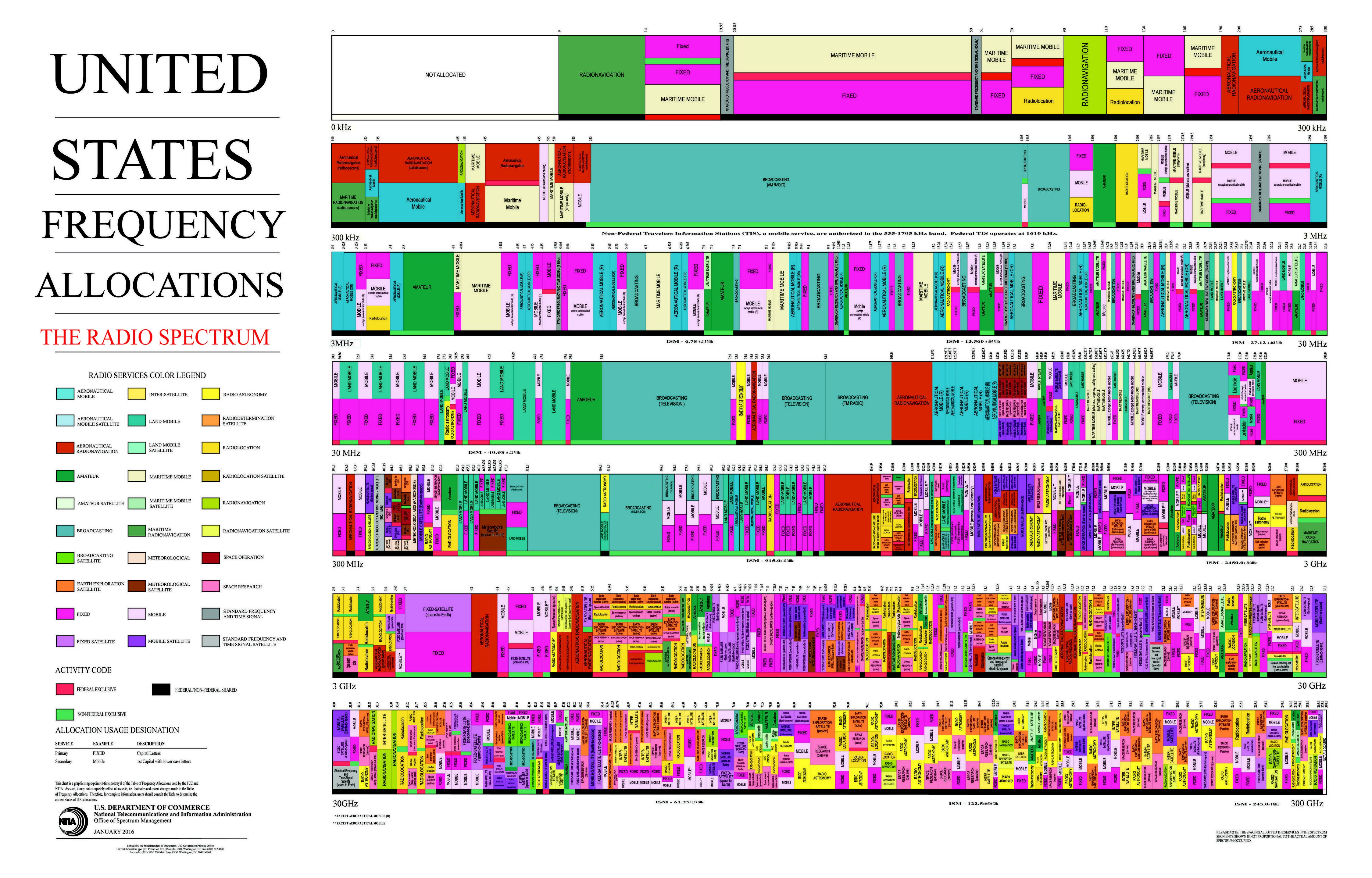
Radio frequency (RF) communication technologies transmit data over the airwaves using electromagnetic waves in various frequency bands. The United States Federal Communications Commission (FCC) regulates and allocates the portions of the RF spectrum designated for different types of wireless services and applications in the United States. The FCC spectrum allocations include bands for cellular networks, WiFi, Bluetooth, GPS, radio/TV broadcasting, satellites, and short‑range industrial, scientific, and medical (ISM) applications. Most wirelessly connected consumer electronics and Internet of Things devices operate in the FCC‑allocated bands between 600 MHz and 6 GHz. The different frequency ranges have trade‑offs between factors like propagation range, bandwidth, interference mitigation, and more. Companies developing wireless‑enabled products must design their systems to comply with FCC technical rules for the appropriate frequency bands. Understanding the FCC allocations provides key insights into choosing and regulating frequencies for reliable, interference‑free wireless connectivity.
The 900 MHz ISM Band
Our wireless protocol operates in the 900 MHz ISM radio band. The 900 MHz band provides an optimal balance of range and throughput for mid‑range wireless devices. Signals in this frequency range are able to effectively propagate across longer distances and through various materials and obstacles. This makes it well‑suited for transmitting wireless data across warehouses, manufacturing facilities, and other industrial environments. In the US, the next higher frequency band available for ISM use is the 2.4 GHz band, which has significantly lower range and penetration power.
Robust Signal Transmission
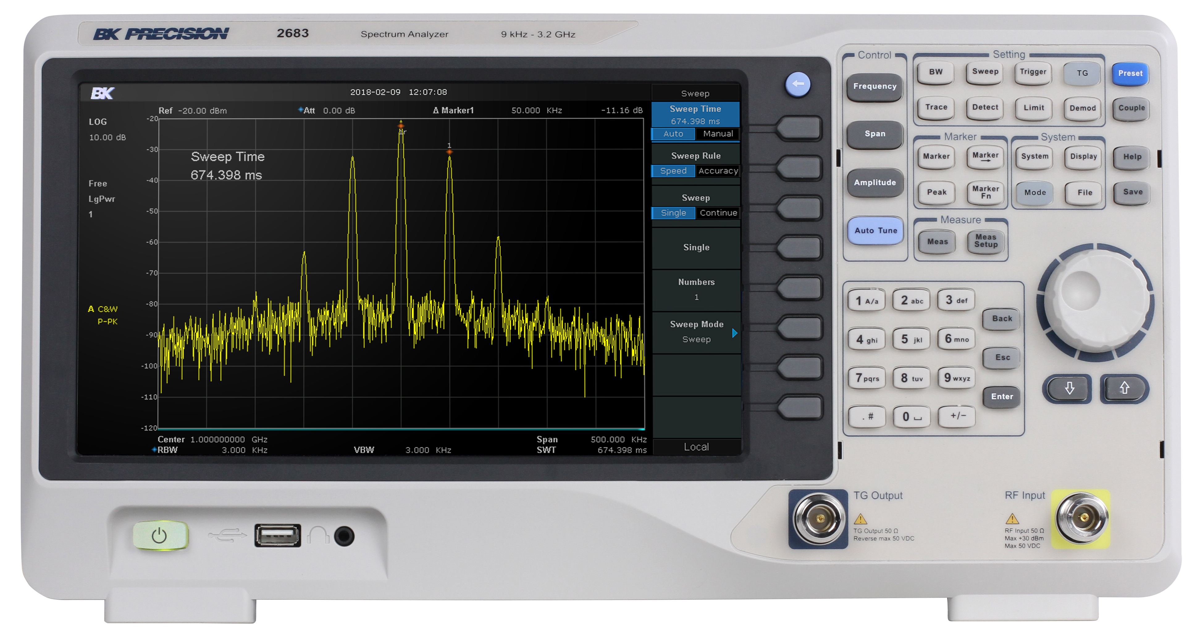
Our 900 MHz protocol implements frequency hopping spread spectrum (FHSS) technology to enhance the reliability and interference immunity of the wireless transmissions. FHSS continuously switches the radio frequency in a pre‑determined sequence known to the transmitting and receiving devices. This allows the wireless signal to effectively evade narrowband interference and multipath distortions. Even in noisy radio environments, FHSS technology maintains solid wireless connectivity. Our protocol consistently jumps between 25 different frequency channels within the 902‑928 MHz ISM band.
In fact, the FCC requires devices operating in the ISM band, even at moderate power levels, to employ a spread‑spectrum technique. One alternative to FHSS is direct‑sequence spread spectrum (DSSS), which widens the transmitted signal’s bandwidth beyond the information bandwidth (and does not require hopping between “channels”). In theory, FHSS is better at compensating for “jamming” or busy frequency bands, as it can simply skip over troublesome channels.
Advanced Encryption
To secure the wireless transmissions, our 900 MHz protocol uses 256‑bit AES encryption. This provides wireless communication that is substantially more secure than Zigbee, 802.15.4, Bluetooth, LoRa, and other short‑range wireless protocols used by competitors. In fact, the federal government does not typically permit encryption shorter than 256 bits for messages containing sensitive data, so AES is a proven standard widely used by militaries and banks worldwide. The 256‑bit key length provides strong protection against brute‑force attacks. The encryption prevents eavesdropping and ensures the confidentiality and integrity of the data as it is transmitted over the air.
Modulation
Wireless communication relies on modulating radio frequency (RF) signals to encode information. There are several common types of modulation used in wireless systems:
- Frequency modulation (FM) varies the frequency of the carrier signal based on the amplitude of the message signal. With FM, the amplitude and phase of the carrier remain constant while the frequency changes. FM is commonly used in radio broadcasting and two‑way radio systems because of its high signal‑to‑noise ratio and resistance to interference.
- Amplitude modulation (AM) varies the amplitude of the carrier wave and is generally not used any more due to its poor noise immunity.
- Phase modulation (PM) changes the phase of the carrier signal and is employed by equipment requiring higher data‑transfer speeds.
Wireless protocols may use a combination of modulation types to transmit data efficiently. The choice of modulation impacts factors like data rate, transmission distance, power efficiency, and signal robustness. Understanding the principles of wireless modulation enables optimizing a system for its intended application and operating conditions.
Paragon uses FM modulation for our equipment. In particular, we use frequency‑shift keying (FSK) modulation, which encodes a 0 symbol as a frequency below the carrier and a 1 symbol as a frequency above the carrier.
Components of a wireless packet
A wireless packet contains several defined segments that enable the efficient and reliable transmission of data:
- The preamble indicates the start of a new packet with a standardized sequence for receiver synchronization.
- The sync word provides frame synchronization by marking the end of the preamble and the start of payload data.
- The payload contains the actual user data. Many wireless protocols divide the payload into header fields for addressing and packet details, as well as the message data.
- A cyclic redundancy check (CRC) checksum is commonly appended for error detection to validate that the packet was received correctly. Packet delimiters may mark the end of the payload and the beginning of the checksum.
- Concluding bits may be included at the end of the message to signify the end of the complete packet.
This standardized framing allows the efficient encapsulation of data into packets that can be transmitted robustly over wireless channels and decoded reliably within receivers. Careful packet design contributes to effective data throughput in noisy real‑world environments.
Paragon’s protocol uses all of the components listed above for communications. Packets are currently capped to carry a maximum of 512 bytes of payload per packet, as the 256‑bit AES encryption can be cumbersome to perform on larger packets.

Antennas and power
Any transmitter must send an amplified signal through an antenna to create RF radiation. This power can be expressed in watts, dB, or other units. For reference, here are typical transmit powers for various wireless equipment:
- Cell phones: 0.4 W
- Handheld radios: 5 W
- Cell towers: 50 W
- Most powerful TV‑station antennas: > 1,000,000 W
- Paragon devices: 0.35 W
It may be surprising to see that cell towers use only about 50 W of power compared with TV stations that exceed a megawatt. If you wonder why they do not use more power, consider that mobile phones must also transmit voice and data back to the tower. Because phones are constrained by battery size and the antenna’s proximity to the user’s head, increasing tower power to extend one‑way range would provide little benefit.
The antenna type influences range. Simple “whip” antennas radiate uniformly in all directions, whereas directional antennas concentrate power toward a specific area. Paragon equips certain models with whip antennas to achieve greater range than the standard “chip” or internal antennas used on other models.

Receiver sensitivity and power budgets
A wireless “power budget” is a calculation method used to determine the approximate wireless range that can be achieved by a system. The calculation starts with transceiver power (in dB) and subtracts all the signal losses in the chain until the signal reaches the receiver. If the received power is greater than the receiver’s sensitivity to the specific data rate and conditions, the receiver will be able to understand the packet.
Due to Paragon’s multi‑data‑rate protocol, receiver sensitivity can reach nearly –100 dBm at the lowest data rate. The transmit power of our N‑Series controllers is approximately +20 dBm, enabling a substantial wireless range for communicating.
Datarate
Digital wireless communications use “symbols” to convey data. A symbol is analogous to a character and can represent varying amounts of information. To achieve higher‑speed wireless data transfer, higher carrier frequencies are typically employed because they can carry more bits per unit time.
As data rates increase, the receiver has less time to sample each symbol, causing its effective sensitivity to decline. This reduces the maximum range between transceivers. The data rate must also be agreed upon by the transmitter and receiver, because a receiver cannot decode a stream transmitted at an unexpected rate.
Paragon employs a “multi‑data‑rate” protocol that automatically switches among four data rates as needed. By adapting the rate, a network can optimize communication for each device. Devices that are close together can use the higher rates to reduce transmission time, while distant devices can fall back to a slower rate to extend range. Modern protocols such as Wi‑Fi and advanced 802.15.4 variants use similar techniques.

Battery life
RF radios typically operate in one of three states: transmit, receive, or sleep. Paragon products draw approximately 80 mA while transmitting, about 18 mA during reception, and 0.002 mA in sleep mode. Maximizing battery life therefore relies on spending the majority of time in sleep.
To extend sleep intervals while still enabling rapid responses, Paragon uses a “super‑beacon” scheme that sends precise timing messages from the gateway. Receivers briefly wake to obtain a few bytes of clock‑adjustment data (compensating for oscillator drift), check for pending messages, and then return to sleep. This approach allows devices to operate for several years on a single battery set.
Regulatory certification
The FCC governs all radio transmissions in the United States (Industry Canada is the counterpart in Canada). North America offers a broad, license‑free 900 MHz ISM band; however, manufacturers must *certify* their devices to ensure coexistence. Regulators focus on preventing interference by limiting power levels, bandwidth, and other parameters that could affect neighboring equipment.
Paragon’s devices are also certified for the European 868 MHz band. This band is narrower than the 900 MHz ISM band, resulting in a modest reduction in data‑rate performance. The CE marking, Europe’s regulatory scheme, also mandates features such as “listen‑before‑talk” for protocols operating in this spectrum.
Conclusion
Our proprietary 900 MHz wireless protocol provides an optimal balance of range, throughput, latency, reliability, and security for industrial environments. Robust modulation, interference mitigation, strong encryption, and low‑latency data transfer create a high‑performance link between devices. This custom‑engineered technology gives our products a decisive advantage over other short‑range wireless solutions.